Showing posts with label Experiments. Show all posts

Saturday, April 3, 2010

Spirals!


Just a quick update. We're busy writing our final report, which is due this Tuesday. But here's the results of our best wire print so far! The spiral is 30 mm in diameter. The wire bonds in two places (the inside and outside) and is supported along the way by a plastic guide. The whole print was done robotically using G-code. We've already demonstrated that we can print wires in straight lines, and now it's clear that we can print curves too!

That's all for now!

Friday, March 26, 2010

Wires pt. 6: G-code control

It's time to take our print head off the bench and do some robotic tests on the machine itself. We've written custom G-code to print out the square with wires, and mounted our extruder. I'll just recap the recent progress.

Having switched to a sturdy 0.5mm pencil, we've found our solenoid mechanism to be incapable of clicking the new device. Anticipating this, I quickly designed a servo clicking system that will accomplish the same job but with excessive force, thanks to the servo's gearing. It's a very crude system: the servo pulls a cable tied to the pencil end once for each click. There's a lot of room for improvement, but at least it's proven to be extremely reliable so far.

A video of the new system undergoing testing:


The job of this mechanism is to advance the wire far enough for it to grab the plastic. Once it's in the plastic, we can just hold the button down and pull the wire any which way by moving the print head. So the wire click speed doesn't limit the wire print speed. What does limit the wire print speed, with the current algorithm at least, is the very long heat-up and cool-down times. We're heating the tip up to 170 degrees to form each bond, then cooling the tip down to 50 Celsius before we move the wire from that point. The thermal mass is not large, but this process takes a long time nonetheless. We can try experimenting with other temperatures too; the current settings lean heavily on the side of "play it safe".


The next step was to try printing from G-code. Mo and Bing have already coded up the commands to print out the test square, . For now, we've taken off Wade's extruder to mount the spoolhead, mainly because we don't want excessive weight pulling on Darwin's cantilevered Z-axis.


The prints we've done from G-code look almost exactly like the prints done by hand, which is a very good sign. The major difference was that the wires kept falling somewhat short of the design length. Watching the print in progress, I noticed that the tip underwent a significant deflection as it travelled horizontally.


From benchtop tests and earlier predictions, we had expected that bending the wire 90 degrees as it prints would take a lot of force; what I'd overestimated was the stiffness of our mounting on the Darwin. Mendel's design puts the extruder between the two rails, which should lead to a huge improvement in stiffness, resolving this issue. But for now, we can compensate by measuring the deflection in X and Y, and adding that distance to our travel, and then moving backward by that amount at the end to un-flex the tip. This should improve our tolerances quite a bit.

We also supsect that the wire guides we posted before may not be necessary at all, because it appears that we don't have to pull the wire down below the top layer to push the wire in. But we'll have to test it to be sure.

So what else is next? Wire cutting, hopefully. The new cutter is ready to use, but I expect that it won't have quite as much strength as the rotating type. Only tests will show if that's the case, though.

Wednesday, March 17, 2010

Wires pt. 4: Benchtop wire-printing

We are operating the wire extruder manually to simulate the wire-printing process, in order to figure out the different variables to control the process, such as such as temperature, extruder height, heating/cooling time etc.

Wire extruder setup

The wire extruder re-heats the plastic surface to make it soft. There were two heat sources: the heat radiated by the screw (which is heated by nichrome wire, just as the plastic extruder) and the heat conducted through the wire. The wire is copper, with a 0.5mm diameter, so it is able to conduct a considerable abount of heat.

Previously we reported failure at attempting to heat the PLA by radiation alone; however, with tip number 2 (all-stainless steel), this is no longer the case - we can now melt the wire into the plastic without contacting the surface. Likely it is the heat conducting through wire that is responsible for most of this success.

==Bond the starting point==

The steps to fix the starting point are:
1 set the z-bed so that the bottom of the wire extruder is 5mm above the plastic surface;
2 click the mechanical pencil to extrude 5mm of wire, so that it touches the plastic;
3 heat up the head to 170 degrees Celsius;
4 wait for 10 seconds for the system to warm up;
5 raise the z-bed 4mm (the hot wire will pierce into the plastic);
6 turn the heat off and the fan on until the extruder temperature is about 40 degrees;
7 hold down the pencil button, so the wire can move freely through the pencil;8 lower the z-bed by a millimetre or two, to allow the wire a suitable bend radius;
9 move the wire extruder to the location of the next bond (in the test we were moving the plastic piece and holding the extruder fixed).

Wire is pierced into the plastic when z-bed is raised

Comments:
the above process makes an accurate, strong and clean bond, so we plan to keep this process for the future testing.

Although project goal is to print 2D wire patterns, we were surprised by how easy it was to "inject" wire vertically into the part. The fact that the wire can pierce through several layers makes 3D wire printing very feasible. We will need to test how deeply the wire can be injected by our apparatus.


== Bond the consecutive points==

1 turn the heat on to 170 degrees;
2 continue holding the pencil button;
3 raise the z-bed until the extruder bottom merges into the plastic;
4 lower the z-bed (now the wire is fixed to the plastic and follows the z-bed when the bed is lowered);
5 switch the heat off and activate the fan to cool the new bond;
5 move the wire extruder to the location of the next bond.


Wire is dragged out when extruder moves (in this test, extruder is fixed so the plastic moves instead)

Wire sticks to the plastic after the z-bed is raised and lowered once

Done!

Comment: the bond is strong (the strength testing is blogged below); however, it's not clean because in step 3 the extruder gets into the plastic surface.
(The good news is we managed to reduce the problem by printing a plastic guide for the metal wire. We will talk about it in the next post. Stay tuned! =) )


== Test the bonding strength ==

PLA impresses Reprappers easily.

It's bio-degradable. It's crystal-clear. It has a very small thermal expansion coefficient (so printed parts almost never warp after cooling).It smells like cotton candy during plastic printing. And plus, its bond with metal is super strong!

In the March 8's post, we showed that various kinds of wire were firmly bonded when they were "push-inserted" into the plastic. Today the wire almost sat on the surface, so we were surprised that the bond was still incredibly strong.

In the following picture, the surface-bonded wire was able to support a 24.5N force (2.5kg weight) without showing any signs of failure. It is now very clear that wire delamination will not be an issue.

Plastic-wire bond
Test weight: 2.5kg

In the near future, the wire extruder will be mounted to the Reprap machine (with its own Arduino extruder controller), sitting in parallel with the plastic extruder. The mechanical pencil will be accuated by a servo motor for now. After we finish writing G-code, the whole wire-printing process will be controlled by the computer. (It may be some quite time before Skeinforge-style software exists to create G-code automatically, because STL files are unfit for wire data).

Saturday, March 13, 2010

Wires pt. 3: Progress on all fronts

(And a few minor setbacks.)


Tests of our first prototype revealed some problems. Mainly, we haven't been able to heat the plastic effectively by convection / radiation alone. We tried making contact with the PLA surface, but this didn't work either: If we let the heater cool and then try to lift it, it stuck to the PLA. If we lifted it before it cooled, the wire pulled out from the still-hot plastic. The heat didn't diffuse very far into the PLA.

The ineffectiveness of the first extruder at heating the plastic lead us to machine some new ones to replace it:


Also, our 0.3mm pencil has proven itself very unreliable at feeding the wire; clicking the pencil doesn't always result in advancing the wire. It could be a problem with the wire, or the pencil itself. Fortunately 0.5mm pencils have proven much more effective, but they are more difficult to click - our solenoid will certainly not have the power. This should be solvable with some re-engineering.


Heater:

So, heat transfer first. I machined two more extruder tip designs. We've abandoned the flange for now, and are using a narrow tip instead. The tricky part is to try to get more heat going down to the PLA than moving up along the steel tube. Thinking about the heat transfer situation we're facing led to this second design, which uses a flared conical tip. Thermal conductance is proportional to cross-sectional area, so the conductance gradually increases along the length of the cone toward the bottom. To do this properly I'd like to do a pen-and-paper calculation, combined with finite element modelling in SolidWorks. But for now I'm just going on intuition. To put it in the language of circuits, the heater tip is like a current divider. I could make a much more complicated and accurate model, but this one illustrates the theory very well:


The PLA surface is assumed to be a heat sink, as is the stainless tube length above the heater. Heat will tend to flow both up and down from the nichrome wire, but we can skew things to make it prefer to flow downward by having good thermal contact to the PLA and having a high thermal resistance going up. I hope that the cone's bottleneck will act as a thermal resistor to keep heat moving downward. Ideally I'd make the bottleneck much longer, but we'll start with this and see if it works before we move to more fragile designs.

So our other new tip uses the same cone design, but the cone is made of alumium and screws onto the stainless shaft. This is done for the same reason; aluminum's thermal conductivity is about 15 times better than stainless, so now the stainless itself should have a high thermal resistance compared with the aluminum path to PLA. Aluminum has the advantage of being easy and quick to machine compared with stainless, but I'm apprehensive about making thin structures from it because it's pretty weak. Also, its high thermal conductivity downward comes at the cost of high thermal conductivity upward. I'm not sure the cone will make much difference here; without a doubt a lot of heat will flow up the aluminum. The thermal contact between the aluminum and stainless is quite poor, but the aluminum piece might be large enough to act as its own heat sink anyway:

So I tried to make it as thin as I could. We'll see. Sometimes it's quicker to just do the experiment than to over-analyze these things.


Mo used a screw jack to manually simulate the RepRap's Z-bed, and mounted the heater nozzle on a clamp. Bing did it up with nichrome and fibreglass just like the real thing, so this test would be more authentic (no more bic lighters). We started with the all-stainless nozzle. Again convection didn't seem to be enough to heat the surface, but when we made contact, the heat penetrated very deep into the PLA. And so did the wire. Penetrating a few millimetres means we can remove the tip while it's still warm, because the wire won't pull out.

(Sincere apologies to SparkFun Electronics for using their logo as a test piece).

Here's a wire bonded this way, by our tip, to a coat hook.


The wire here is 24-gauge (0.5mm) tinned copper, from McMaster-Carr. It fits beautifully in a cheap 0.5mm pencil, but the best thing is that it's not insulated like magnet wire, so it might actually be useful. The downside is that it's quite stiff, which might make it hard to print with. Our impression is that if we bond it at regular intervals and when going around bends, we shouldn't have too many problems.


The aluminum tip will be tested next.


Cutter:

These tips don't yet have cross-drilled holes for the rotating cutter. But with Bing's observation that the cutter seems to act as a powerful heat sink, it might be worth considering a back-up plan. I'm thinking of using the solenoid directly; solenoid bars come with holes drilled in them already.


We'd lose the mechanical advantage, but when it comes to solenoids I'm not sure that's such a bad thing. A solenoid ideally has a force proportional to the inverse square of the pull distance (although for very small pull distances, magnetic saturation makes it more linear). With a mechanical advantage of 2, we'd amplify our force by two but need to pull over twice the distance, so at the far extent the force the solenoid can provide will drop by a factor of four. It's hard to tell at this point whether it's beneficial or not, because the strongest force is really needed right at the end of the pull, when the wire gets cut, where the mechanical advantage and solenoid non-linearity work together to provide a strong force.

So it could go either way. At least it's worth keeping this alternative in mind. It is, after all, a fair bit easier to build.

Wednesday, March 10, 2010

Wires pt. 2: Tip Prototype #1 Machined


Less than three weeks remaining before our project is due! Time to get a move on.

After a few hours in the UBC Student machine shop, we've built the extruder tip. Machining this piece from a stainless steel screw required some special cobalt drills (available at the hardware store), because normal drills broke repeatedly. A lathe is highly recommended for doing the drilling, although conceivably it could also be done with a drill press.

As you can see, we've modified the end of the screw to keep nichrome wire as close as possible to the printed part. This required a significant amount of machining, but the benefit is not yet certain. If time permits, we will test out simpler variations (more easily produced in a basement) that reduce the machining requirements.

This tip serves two purposes - if it weren't for these requirements, we'd just hook up the mechanical pencil and be done with it all.

- Mount the nichrome wire heater close enough to the plastic surface to heat it effectively, and far enough from the spoolhead to protect it from the heat
- Mount the wire-cutting mechanism

Heating:

The initial design was to simply have nichrome wire wrapped around a smooth tip very close to the end. However we found during our plastic extruder experiments that it can be tough to keep the nichrome fixed in place, so we added a lip/flange to the design to help wind the nichrome. Now since the material is stainless steel, the flange acts as an insulator between the nichrome and plastic, which is bad because we want as much heat to flow downward as possible. So the flange was made to be as thin as possible (<0.5mm), since the thermal resistance of a part is proportional to its thickness in the direction of heat transfer. Then, since we had the tools available and it would only take a few minutes extra, we thought we'd further reduce the flange's insulation by drilling holes in it. This led to the idea of weaving the nichrome through the holes themselves, in order to get it as close as possible to the plastic surface. But concerns about the wire biting into the insulation led to coating the nichrome with kapton. However, this combination led to rather sparsely-wound nichrome wires, so when we tried to heat the plastic build surface with this setup, it was not effective. It was also difficult to insulate the nichrome, because there wasn't much room. We'll try out some other configurations soon -- I think the original plan might still work the best.


Cutting:

For those who haven't read about SpoolHead on the wiki, the idea is to use a rotating cutter inside the main tube. Basically you drill a hole through the tube and put a narrow rod inside, which also has a hole in it (preferably wider at one end, so that it only cuts the wire in one place). The holes normally are aligned, but when the rod undergoes a rotation, the wire is sheared in half.

We could easily use more standard available parts, but being in a hurry, we could not wait for an order of 3mm diameter rods to arrive. So I quickly cut one from brass, filed it flat on either end and drilled the hole (halfway with a 2.3 mm drill, and the rest with a 1.2mm drill).

The cutter design would probably work best with a steel cutter. However, stainless-on-stainless gives very high friction, and I didn't have scrap tool steel on hand. I wouldn't want to use this brass piece to cut piano wire, but it seems to work just fine for copper. One potential modification would be to tap a 2mm screw thread in the brass cutter, and use a drilled-out set screw as the "blade". That would probably work quite well, combining the hard cutting edge of steel (replaceable, too) with the machinability and low friction of the brass rod.


We tried it out by hand. It worked! The mechanical advantage here is about 13 (1.5mm from the fulcrum to the cutting edge, 20mm to the pulling point) and the thin wire isn't that strong to begin with, so it sheared the wire cleanly and effortlessly. (It remains to be seen, of course, if our wimpy solenoid will be able to do it though).


Monday, March 8, 2010

Wires pt. 1: More Benchtop Experiments

The SpoolHead concept relies on several untested ideas, both specific to our implementation, and also fundamental in concept. As it stands, these are:

1. The wire can be controllably fed by clicking a mechanical pencil
2. The solenoid we've chosen will be strong enough to click the pencil
3. The wire can be firmly bonded to the plastic part by melting the PLA surface and inserting it
4. Our heater design will be able to melt the PLA surface without contacting it
5. The wire can be cut by our rotating cutter without fouling the device
6. The solenoid we've chosen can actuate the cutter
7. The wire can be bent and dragged without serious difficulty

This is enough question marks to make any design engineer nervous. It all works just fine in my head, but will that match reality?

To get some certainty, we've decided to perform another series of benchtop experiments. The biggest assumption is number 3: The wire can be firmly bonded to the plastic part by melting the PLA surface and inserting it.

If this turns out not to be the case, then our whole design needs to be re-evaluated to make use of a new material, such as superglue or UV-curing resin. That would be a considerable setback.

Bing melted some PLA with a lighter and pushed in some 0.3mm magnet wire. It went in easily with little force, which was good (a mechanical pencil can hardly supply any, and even if it could, the wire might buckle if too much force is applied). It was pushed in to a depth of 3mm. We let it cool for 20 seconds, and gave the wire a tug - it didn't budge. That was a good sign: the quality of the bond between the PLA and wire surface - in this case, enamel insulation - appeared to be quite good.


To see just how good, we started hanging weights from the wire. At 590 grams, the wire snapped - but the bond held firm. That means that the bond was stronger than the wire, and held at least 2N/mm along its length (quite likely more).


We tested again with other wires: 0.25mm steel piano wire, and bare 0.1mm wire. These results were also both similarly successful, although the piano wire was stronger than its bond (unsurprising, given how strong that wire is). That bond also held over 2N/mm, failing when the whole assembly was jerked upward. The 0.1mm copper wire was a very good test, because its stiffness is extremely low (like a sewing thread); thus, the fact that it could also be push-inserted without buckling is very encouraging. The copper-PLA bond held tightly as well.


Why are we concerned about bond strength? Our printing algorithm is to click the wire forward until it has bonded to the surface at one point, let it cool, and then rely on the strength of that bond to feed the wire further as the print head moves in a straight line.

As a side note, the 20 second cooling time was probably longer than necessary; the bond already felt stiff to a gentle tug by 10 seconds.

Conclusion: Bonding wire to a heated thermoplastic surface appears to be a promising and viable method.

More testing to come...

Wednesday, February 24, 2010

Extruders Pt. 2: Add oil


In China, you can encourage someone to work harder by saying "加油!" (jia you), which means "add oil". Apparently that's encouraged our extruder to work harder as well, because adding oil did just the trick. A drop or two of machine oil, applied sparingly to the inner surface of our stainless steel tube on a scrap piece of PLA filament, has got everything finally working smoothly.

I should add that our plastic extruder nozzle tip diameter is unusually large; this is done "just to make sure it works". As the plastic printing is a secondary aspect of our project, we're not too concerned with plastic print resolution and precision for now. On the other hand, an oversized nozzle gives us something like twelve times the print speed, allowing for the printing of bigger objects. Which leads to one of my other observations; perhaps in a multiple-print-head system, a fine nozzle could be used for printing the part perimeter, while a fat one handles the infill. The infiller could even be something as simple as a glue gun running on hot glue, which would actually be quite ideal (cheap, widely available, tough, sticky).

While backflow was undoubtedly an issue in our old extruder, some problems persisted in our new, tight tolerance one. The plug was gone, but extrusion would still fail after cooldown. To see if backflow was causing the problems again, we tried this procedure:

1. Feed fresh PLA
2. Heat up
3. Cool down
4. Heat up
5. Attempt to extrude

As predicted, it was unable to extrude upon reheating. No attempt was made to extrude on the first warm-up this time, so there would be no pressure to cause backflow. If backflow was still occurring it would be due only to the capillary effect. To see if this was causing the problem we removed the filament for postmortem analysis; however, no plug was visible. The diameter was very slightly wider near the tip, where it had warmed up.

We concluded that the softened PLA either had too much friction with the stainless steel surface, or was able form some kind of chemical bond to it, and this was strong enough to prevent extrusion.

Adding a drop of machine oil to the extruder resolved the problem nicely, either by lubrication or by physically preventing the chemical bond. You might ask if this would foul up the extruded PLA, but the oil doesn't appear to get consumed; it apparently stays inside, clinging as a thin film to the steel surface.

In summary: If you find that you can successfully extrude for a little while using a fresh piece of plastic, but it jams the second time, "加油!"

Tuesday, February 23, 2010

Extruders Pt. 1: Backflow and Bench Experiments


Our work on the SpoolHead has been put on hold as we troubleshoot our plastic extruder. What would happen is that the extruder would work great on a fresh piece of PLA, but when we left it to cool and ran it again, it would be unable to extrude (even with Wade's geared extruder providing massive amounts of force). What could explain the extruder working perfectly at the beginning, and grinding to a halt the second time?


We're hoping to fix this as soon as possible, because no doubt there will be much troubleshooting of the SpoolHead as well. To understand the problem, we've been conducting some benchtop tests, observing how the PLA behaves inside the extruder nozzle.

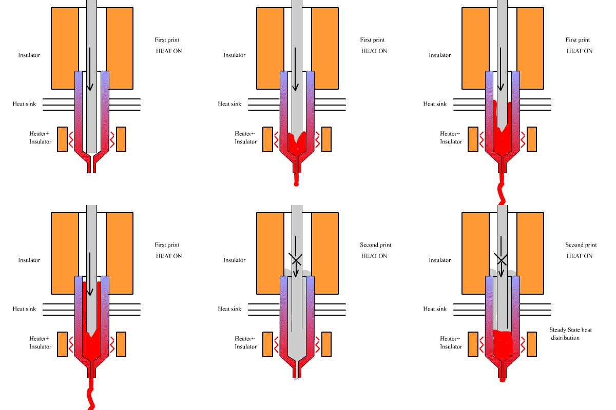
Bing conducted experiments to determine why, after five minutes of successful extrusion, subsequent cooling and re-heating of the extruder caused it to fail. From our experiment, the resistance to flow due to viscosity through a narrow aperture is actually quite small; however, with the current Reprap-standard extruder design, a far more significant problem occurs. Because the nozzle is drilled wide, there is a void between the filament and the metal which fills with molten plastic. Even with a steep temperature drop at the front of the nozzle, and heat sinks, the plastic retains enough of its thermal energy to flow back up the nozzle and cool in problematic places. Indeed, steepening the temperature gradient with heat sinks seems to exacerbate this issue, because it becomes impossible for heat to reach this cooled plastic.

The problem is that the process is not quasistatic; because of the hot plastic's ability to flow rapidly up the nozzle before it can cool to the same temperature as its surroundings, the temperature distribution inside the extruder is not the same on the first run as it is on the second.

Here's how I visualize the process:
(This figure represents the extruder setup we were using, which had heat sinks to provide a steeper temperature distribution).

What to do about it?
The best solution would probably be Nophead's, which is to have a cone opening outwards, so that pressure on the fluid forces the plastic further outward, rather than back up the nozzle. However, I believe it is also important to maintain as small a void space between the barrel and the filament as possible. That means maintaining tight tolerances, both on the drill diameter of the extruder nozzle, and the filament itself. (Not all PLA filament is created equal.)

Using a PEEK insulator, which bonds relatively well to molten PLA, is probably not the best idea also. Having, if possible, a seal at the transition to the insulator would be of use as well. PTFE's tendency to flow is useful in this regard. We have made a PTFE insulator that is slightly under-drilled right at the end, so that it seals firmly against the plastic. Hopefully this will prevent backflow.

For now, we are also planning to have a wider nozzle at the tip, which will reduce the pressure that causes backflow. This will reduce our part-printing precision, but that's not really a concern for the SpoolHead project, because the plastic extruder merely needs to work.